Metro Nashville Fire Department

A new homefor our heroes

Headquarters and Fire Station 2

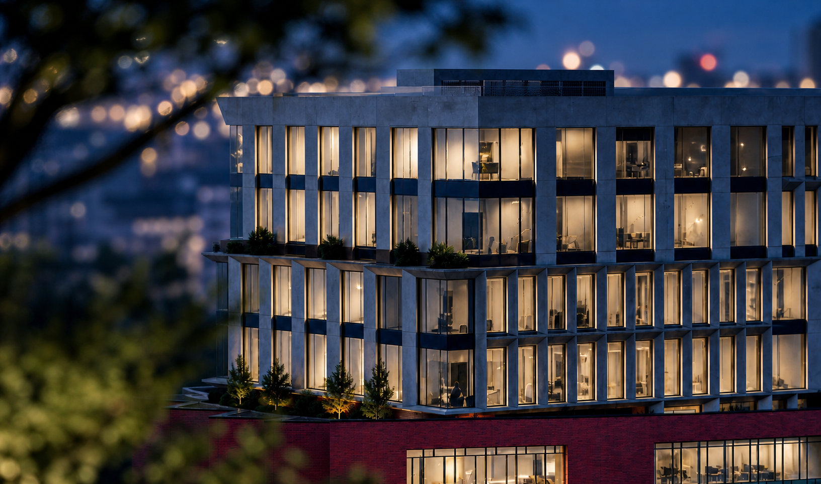
Upper office volume and facade openings

The project

One connected facade

The fire station, headquarters and office building share one facade plan.

555'-4"
Roof elevation
13'-4"
Typical floor to floor
24'-8"
Typical tall unit
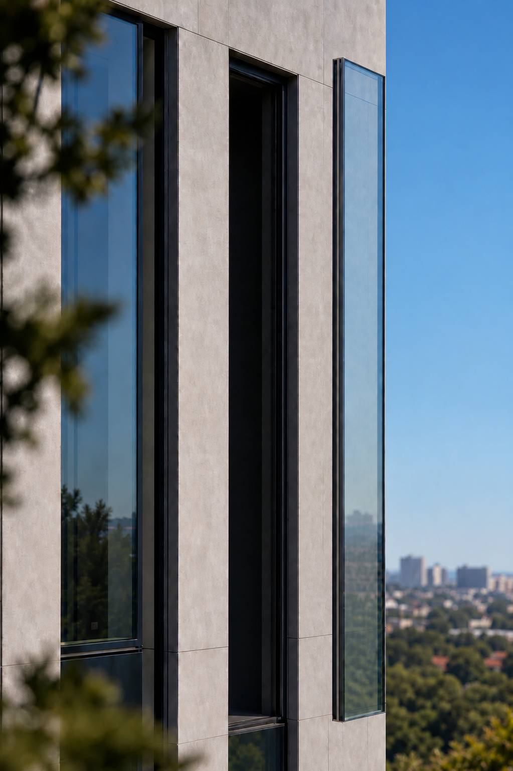
  • Tall windows serve the upper floors.
  • Terraces step back above the working base.
03
Typical tall glazing unit in the project model

Our scope

The facade scope

1CG coordinates the glass, panels and the places they meet.

42,752 SF
Facade glazing
2,900 SF
Doors and louvers at grade
940 SF
Terrace railings
  • All floors, including ground level: factory-built glass and panel units.
  • Entrances, base-bid storm-rated louvers, terrace rails and ACM coping.
  • Perimeter seals, flashings and connections.
  • Brick, signage and logo etching: excluded.
  • Bi-fold apparatus doors: separate alternate.
04
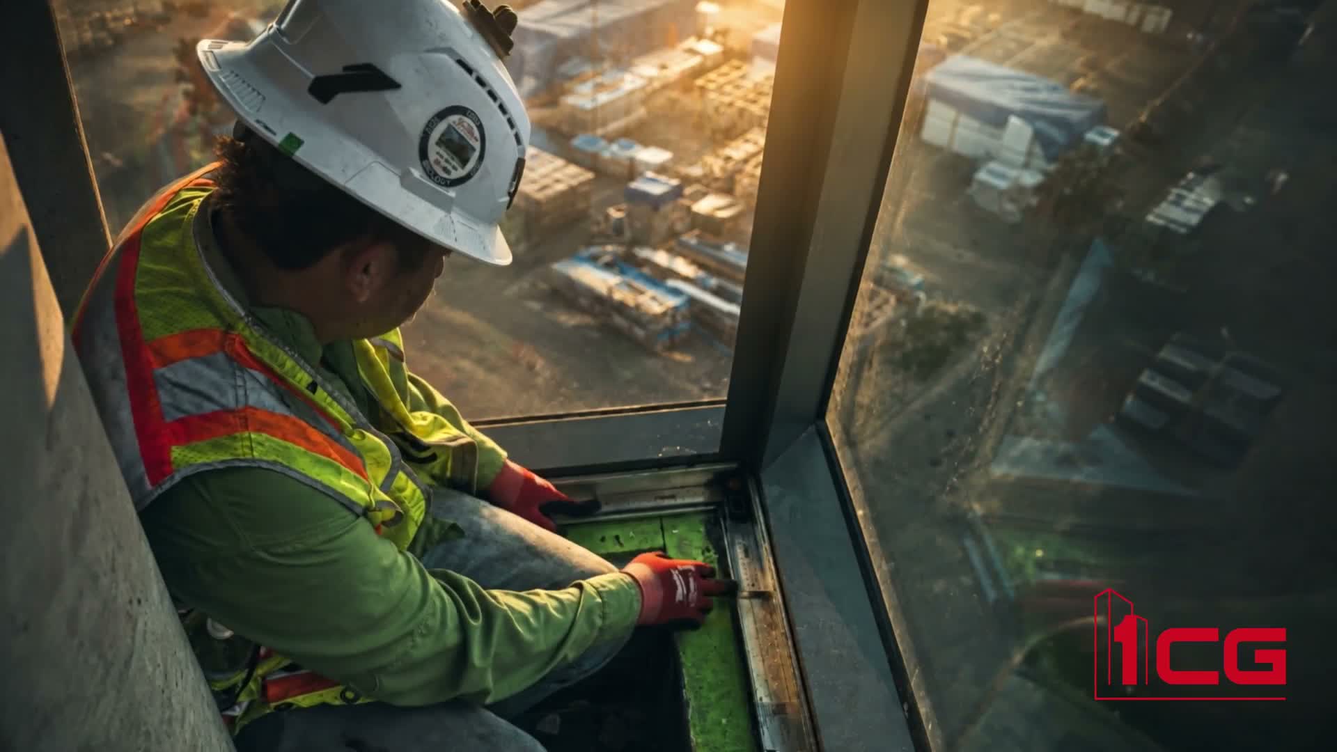
Facade installation shown in the standalone 1CG brand film

1CG + IGS

The people behind the work

One team connects design, manufacturing and installation.

Tony

Unitized-glazing experience in the US and overseas, including three supertall projects.

10.8M SF domestic8.8M SF internationalSelected experience: Freedom Tower, Shanghai Tower and projects in the UAE.
1CG

One point of contact for the facade, from drawings through closeout.

About 1.6M SF of glass experience with IGS

IGS

IGS is a U.S.-based company with manufacturing plants in Turkey, supporting glass, panels and factory-built units.

Production, packing and shipping coordination
—
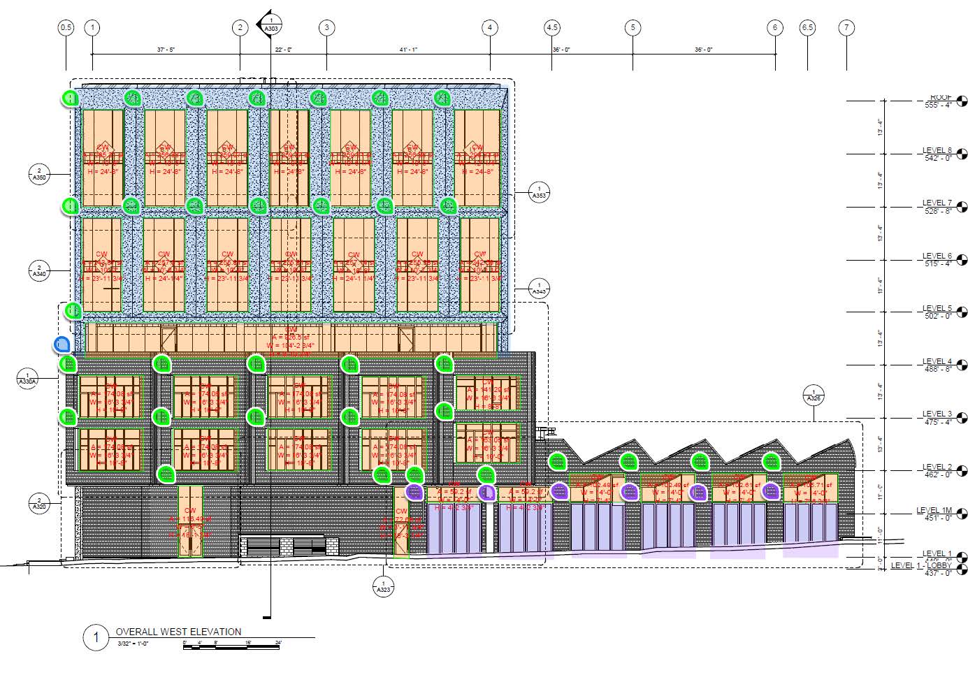
West elevation
West elevation
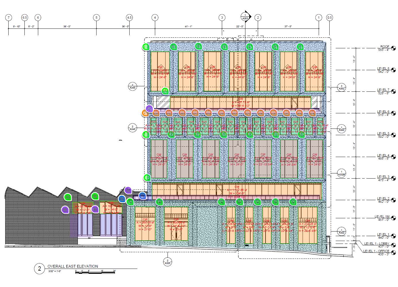
East elevation
East elevation

Project drawings

West and east elevations

Opening sizes and panel joints follow the elevations.

05
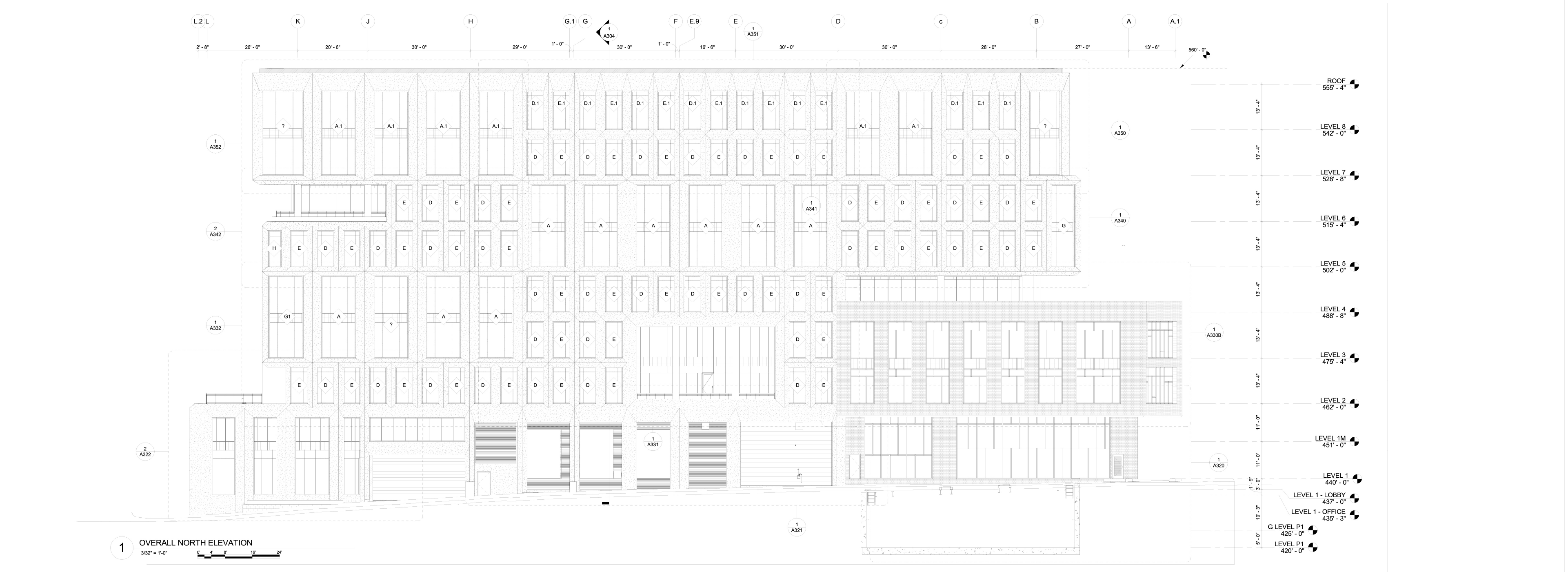
Overall north elevation
IGS · C02 · Detail 1
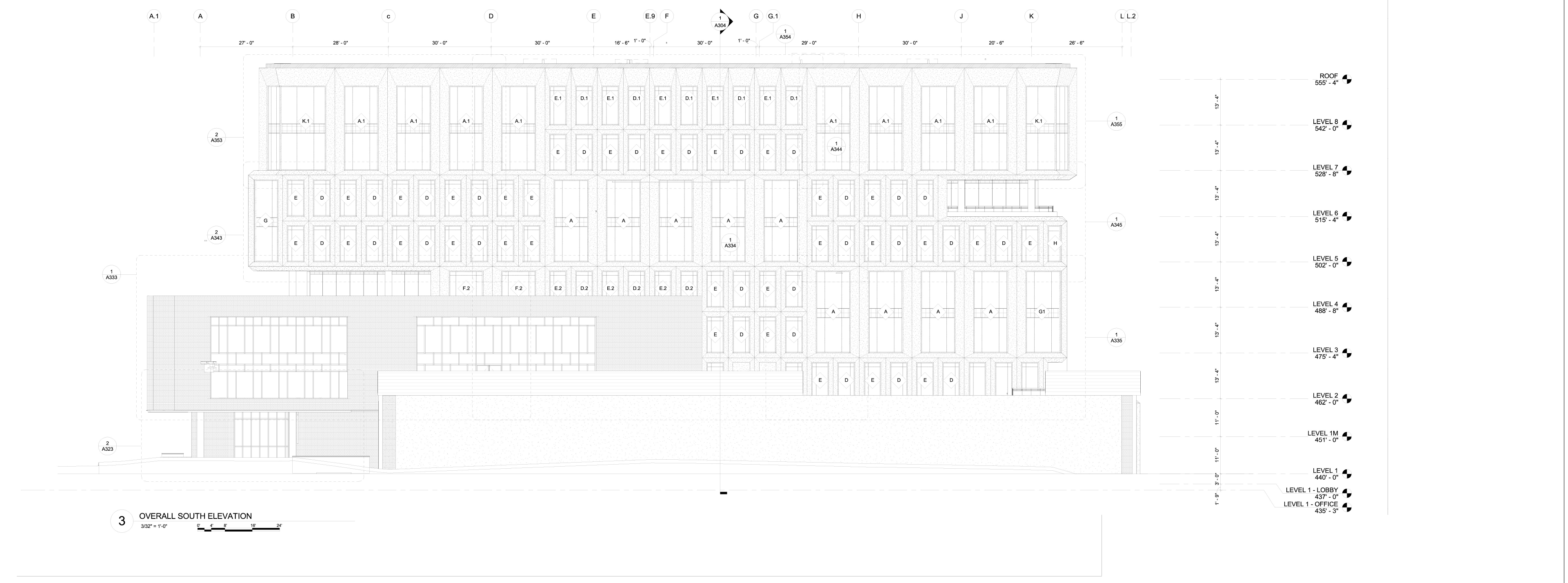
Overall south elevation
IGS · C02 · Detail 3

IGS project elevations

North and south elevations

North and south elevations coordinate the window grid, stepped terraces and apparatus base.

06
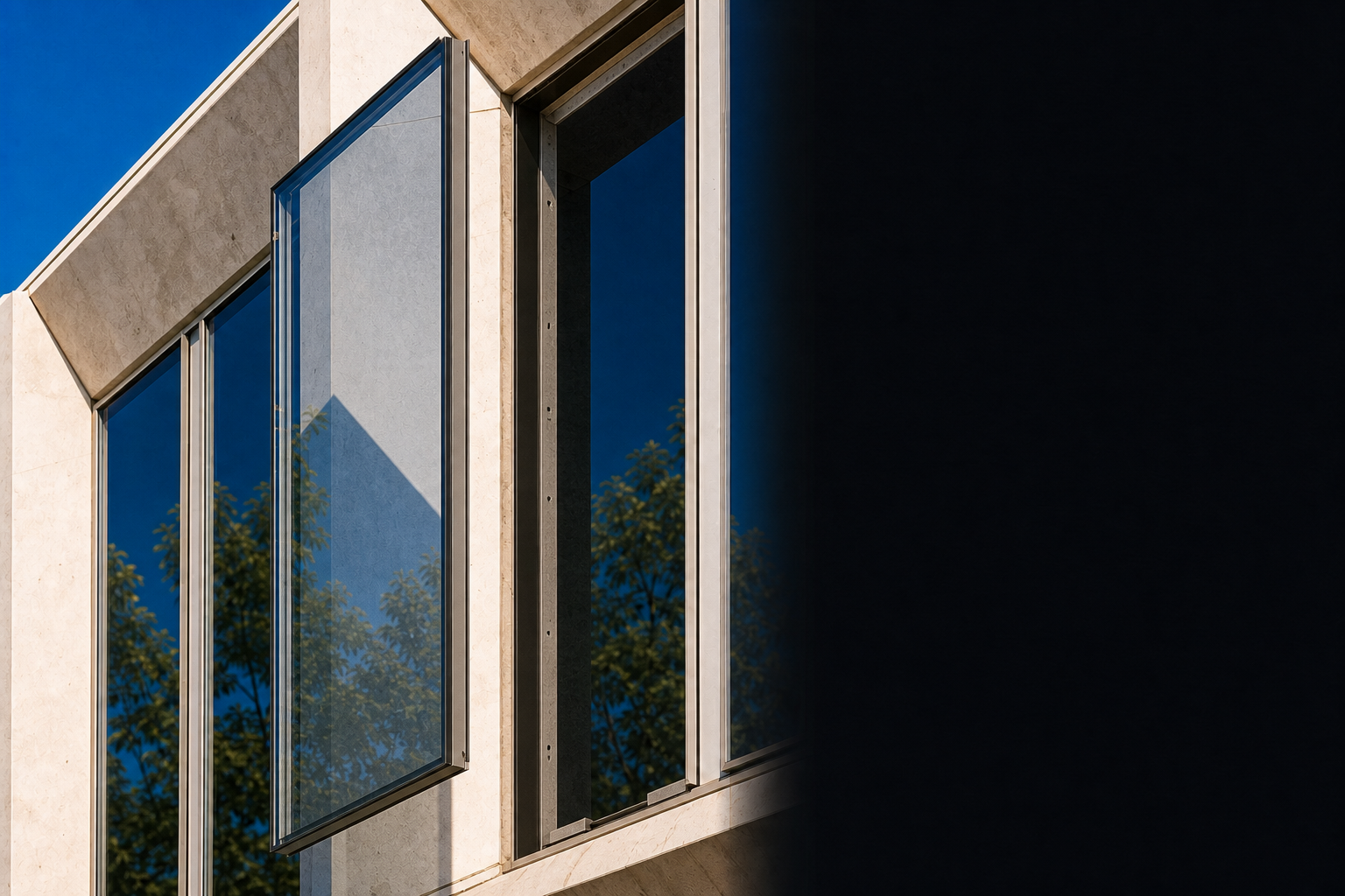
Project glazing and window detail

Performance basis

Built for the required loads

The glass, frame and anchors must work together under the governing load.

Level D
Missile criterion
1-5/16 in.
Current impact IGU basis
ASCE 7-22
Chapter 32 tornado basis
  • Risk Category IV is the project basis.
  • Evaluate tornado and code wind loads. The larger case governs.
  • The structural glass interlayer carries the impact requirement.
07
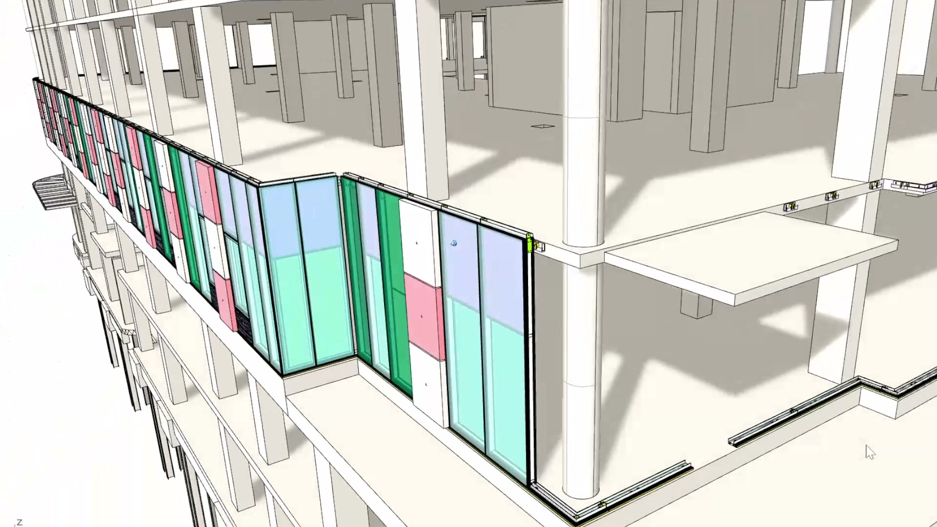
Still from the supplied model installation video

Glass and framing

Built in the factory. Set on site.

Glass and panels arrive as coordinated, factory-built units on every floor, including the ground floor.

AAMA 2604
Powder-coat basis
20 years
Finish warranty basis
10 years
System and glass warranty basis
  • IGS is U.S.-based, with manufacturing plants in Turkey.
  • Set glass, gaskets and finishes before delivery.
  • Plan tolerances and connections together.
08

Assembly in motion

The system comes together

Glass, framing and panels align as one assembly.
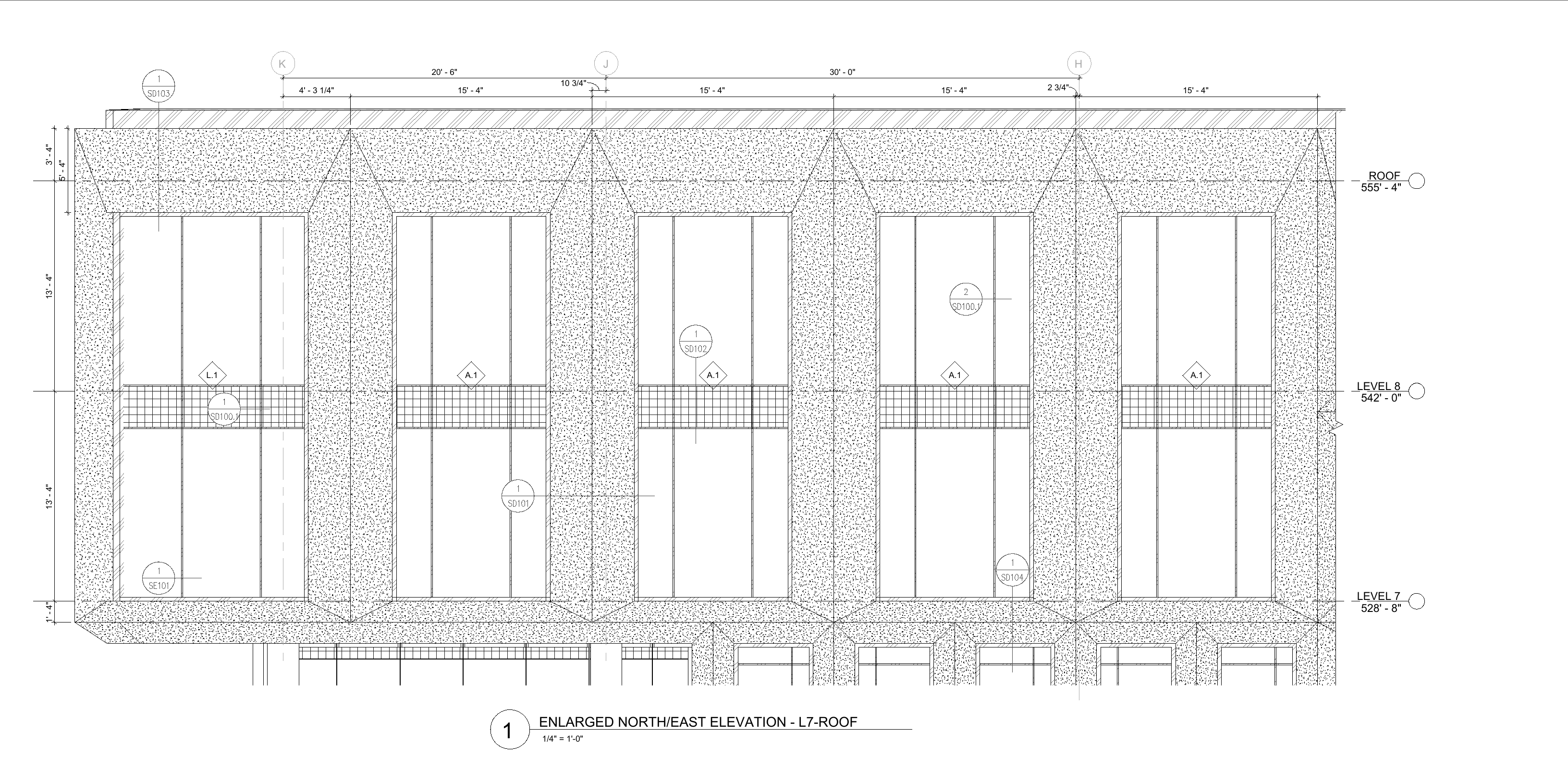
Enlarged north/east elevation, Level 7 to roof
IGS · C03 · Detail 1
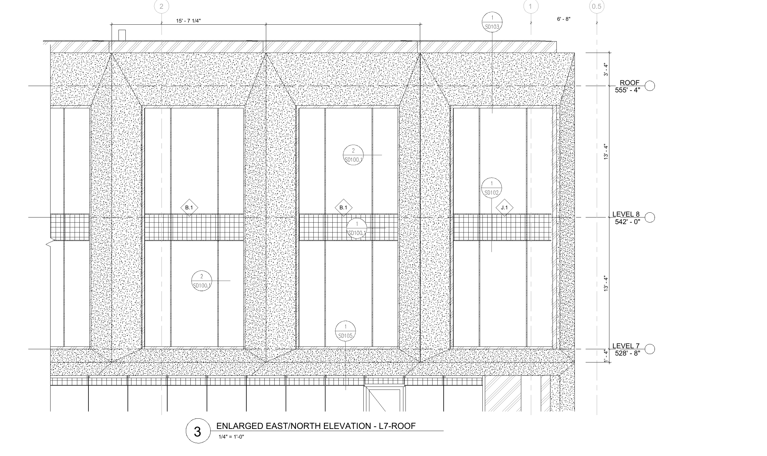
Enlarged east/north elevation, Level 7 to roof
IGS · C03 · Detail 3

IGS enlarged elevations

The upper-floor facade

Enlarged elevations show how the panel profiles frame the glazing from Level 7 to the roof.

  • Glazing and panel alignment
  • Level 7 through roof
  • Dimensioned bays and grid lines
10
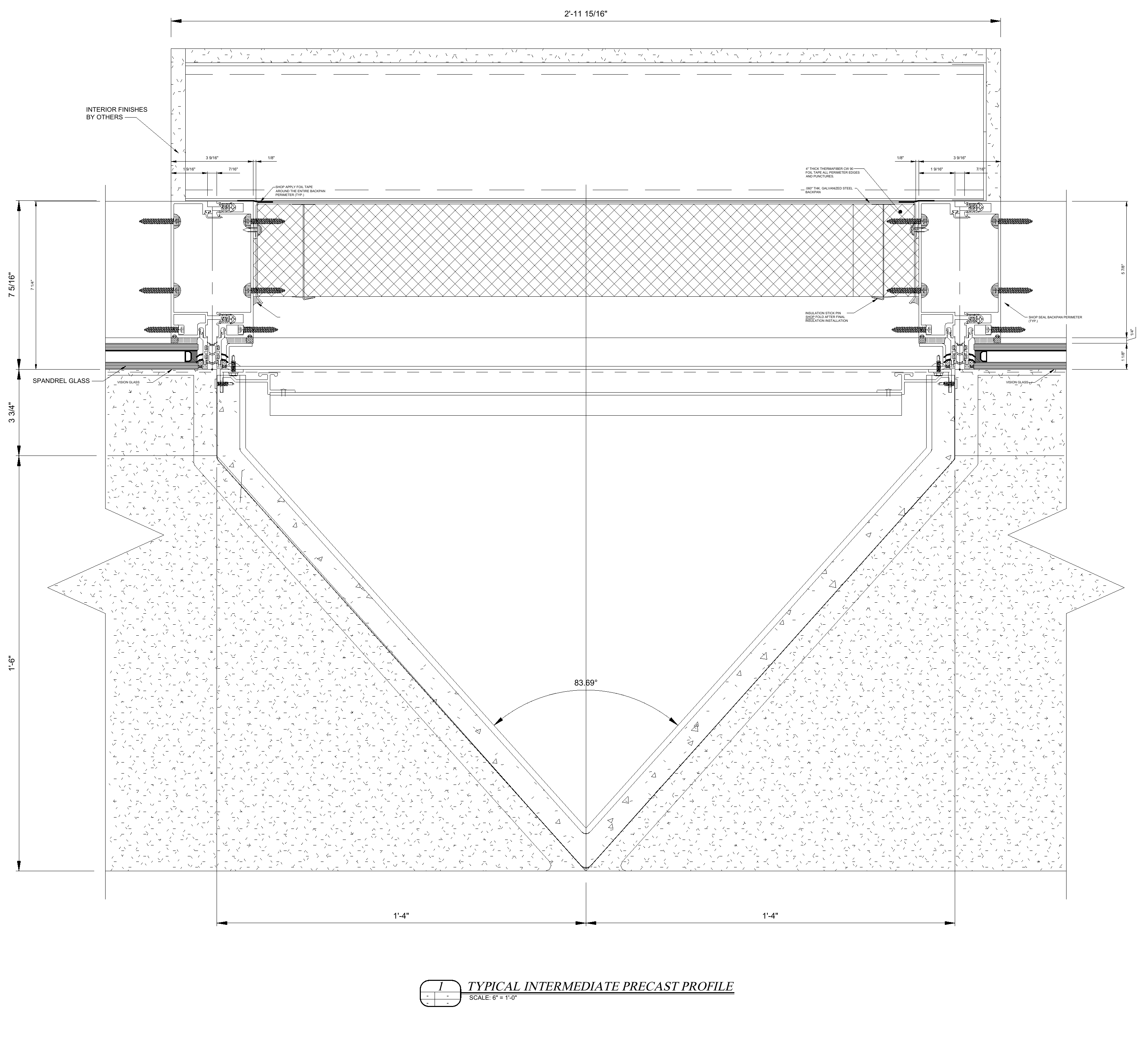
Typical intermediate precast profile
IGS · SD101 · Detail 1

IGS profile detail

The panel profile at the window

The profile detail shows the glazing, insulated backpan and angled panel returns in one section.

  • Vision and spandrel glazing
  • Insulated backpan
  • Interior finishes by others
11
Typical precast profile, 16-inch symmetrical, at Level 3
IGS · SD104 · Detail 1

IGS profile detail

The Level 3 panel connection

The symmetrical profile meets the glazing and adjustable anchor assembly at Level 3.

  • 16-inch symmetrical profile
  • Embed channel and anchor slide
  • Vertical adjustment bolt
12
Project model of apparatus-bay and grade-level openings

Doors and louvers

Openings at ground level

Doors, louvers and storefront must work with the building’s access and security systems.

2,000 SF
Bi-fold door alternate
900 SF
Storm-rated louvers
  • Coordinate locks, wiring paths and access control.
  • Confirm automatic operators where required.
  • Bi-fold apparatus door pricing is a separate alternate.
  • Storm-rated louvers are included in the base bid.
13
Supplied vision-glass detail

Vision glazing

The glass makeup

Deep Silver glass sets the look. A structural interlayer supports the impact requirement.

  • Outer lite: 8 mm Ecosol T 35 Deep Silver.
  • Space: 12 mm, filled with 90% argon.
  • Inner laminated lite: 6 mm ultra-clear glass with a .090 SGP interlayer.
  • Confirm vision, spandrel and impact build-ups, plus thermal values, before release.
14
Vision mullion pair with gasket, sealant and glass-edge protector
IGS · SD100 · Detail 1

Framing detail

The vision-glass joint

Male and female aluminum mullions join adjacent vision-glass units around a primary vertical gasket.

  • Paired aluminum mullions
  • Primary vertical gasket
  • Sealant and glass-edge cap
15
Spandrel mullion pair with insulated galvanized steel backpan
IGS · SD100 · Detail 2

Framing detail

The spandrel joint

The spandrel joint combines the paired frame with an insulated, shop-sealed steel backpan.

  • 4-inch Thermafiber CW90
  • .060-inch galvanized backpan
  • Shop-sealed and foil-taped edges
16
Typical slab anchor with embed channel, adjustment bolt and lateral stop clip
IGS · SD102 · Detail 1

Framing detail

The slab connection

The embed channel and anchor assembly connect the unit to the slab with vertical and in/out adjustment.

  • Slotted anchor base plate
  • Vertical adjustment bolt
  • Field-installed lateral stop clip
17
Roof profile section, rotated upright
IGS · SD103 · Detail 1

Framing detail

The roof connection

The roof section brings together the coping, water line, insulated enclosure and slab anchor.

  • Coping and water line
  • Foil-faced CW90 insulation
  • Firestop interface at the slab
18
Typical stack joint between vision and spandrel units
IGS · SD106 · Detail 1

Framing detail

The joint between units

The horizontal stack joint connects the vision unit above to the insulated spandrel zone below.

  • Interlocking frame profiles
  • Vision-to-spandrel transition
  • Shop-taped backpan perimeter
19
Spandrel-to-vision intermediate horizontal
IGS · SD106 · Detail 2
Vision-to-vision intermediate horizontal
IGS · SD106 · Detail 3

Framing details

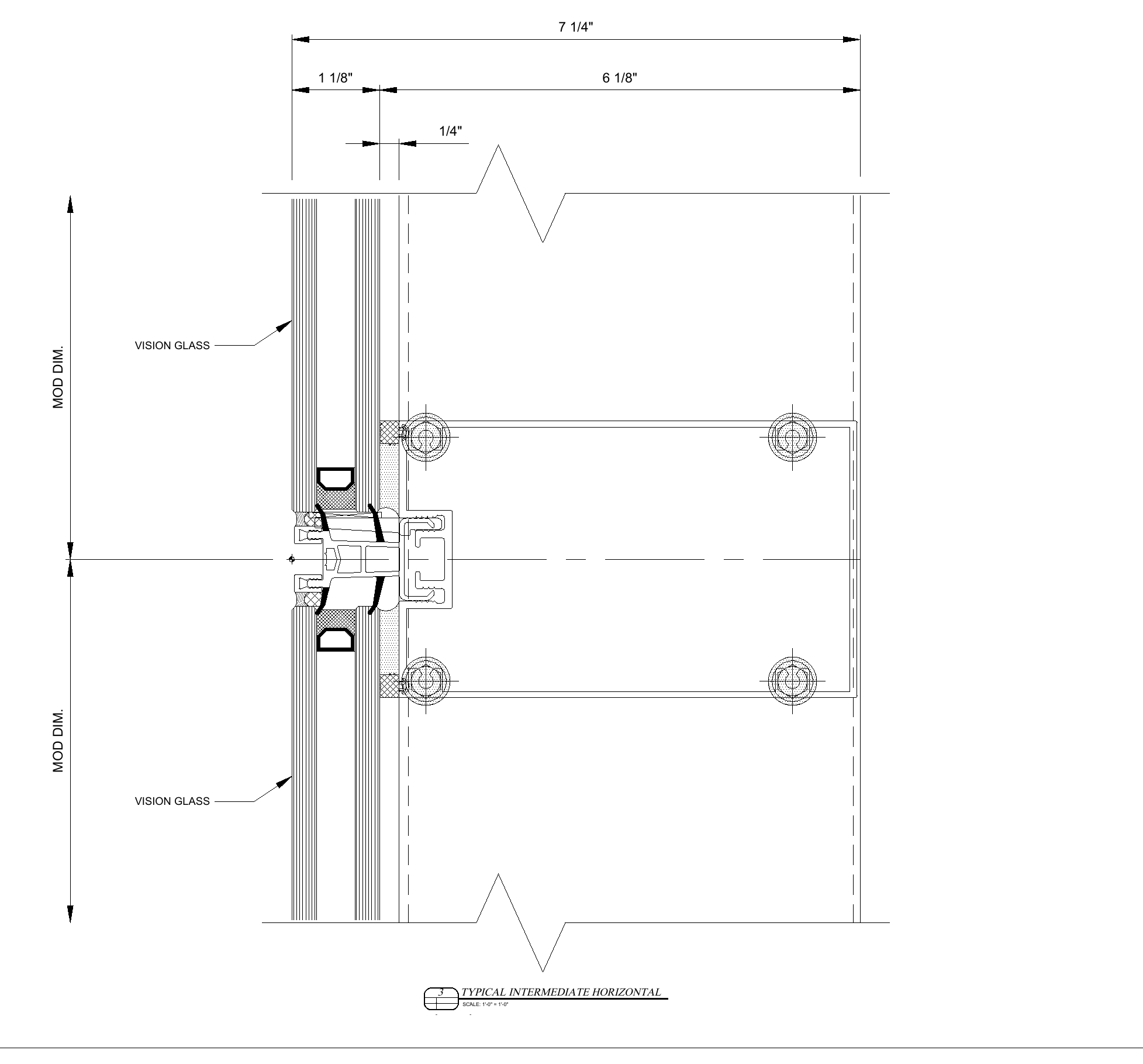
The intermediate joints

The two horizontal details show the frame connections at spandrel-to-vision and vision-to-vision transitions.

  • Spandrel-to-vision joint
  • Vision-to-vision joint
  • 7¼-inch frame depth shown
20
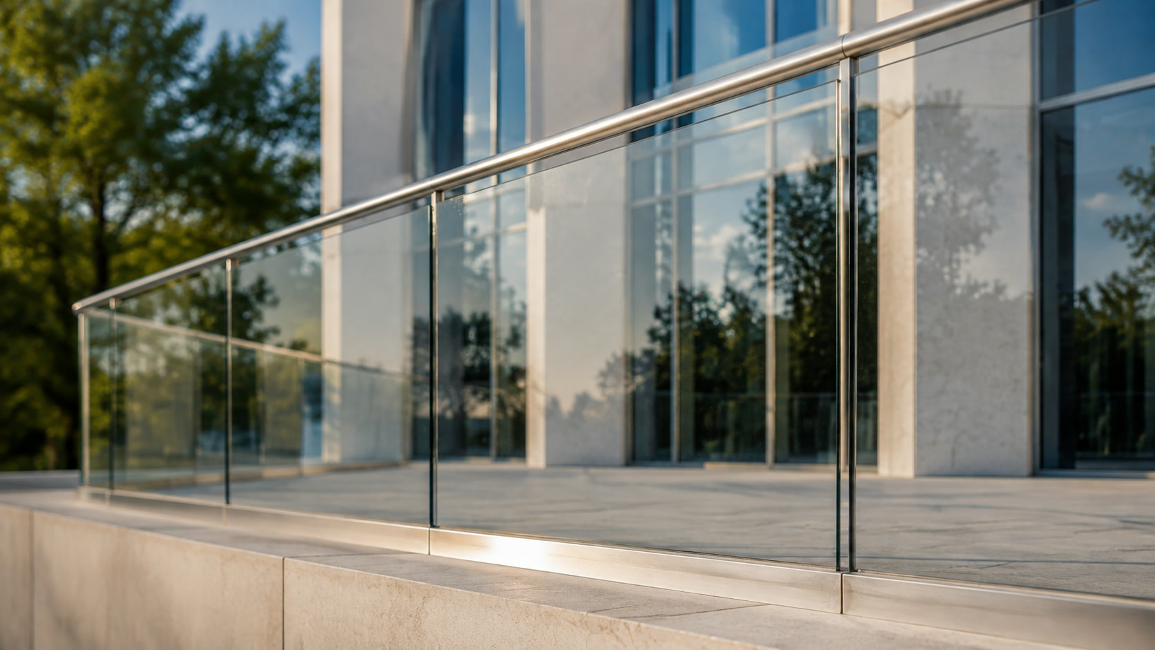
Illustrative terrace glass guardrail and tube handrail

Terrace railings

A clear terrace edge

Glass and tube rails follow the stepped terraces.

940 SF
Glass and tube railings
  • Coordinate anchors, guard heights and slab edges.
  • Keep the waterproofing continuous at each fixing.
21
Panel and glazing interface at the facade corner

Perimeter details

A continuous water line

Seals and flashings must connect across every change in material.

  • Carry coping across the parapets.
  • Detail flashings at heads, curbs and louvers.
  • Connect concrete, masonry, metal, roofing and waterproofing.
  • Maintain two complete perimeter sealant lines.
22
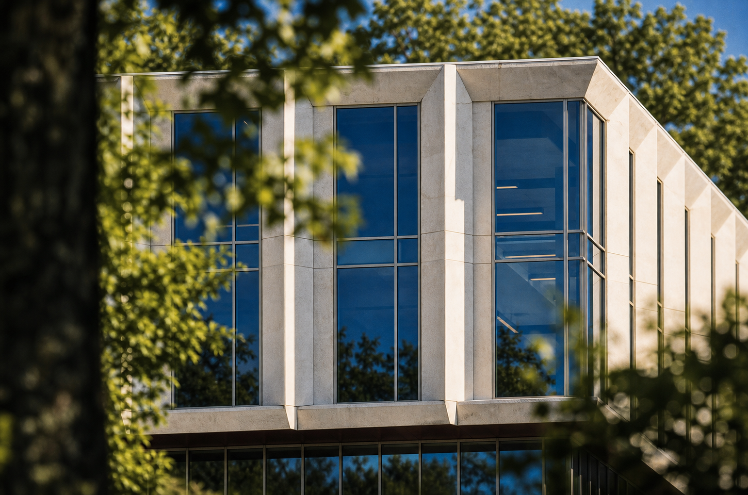
Architectural reference for integrated panel and glass geometry

Material alignment

Glass and panels in one grid

Deep Silver glass, light panels, coated aluminum and the red soffit form one facade.

  • Align panel joints with the window grid.
  • Resolve returns, corners, coping and base connections before release.
23
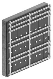
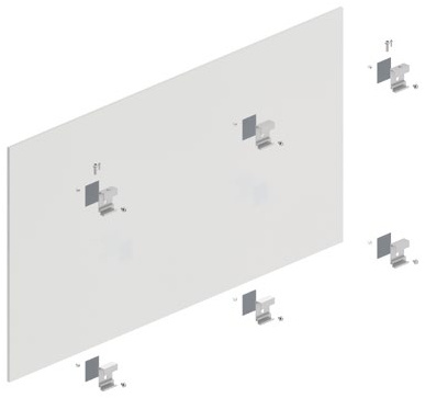
Manufacturer view of the panel back and concealed fixings

DKT1 panel system

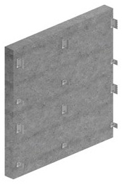
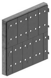
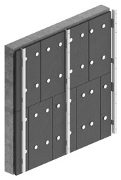
How the panels are held

Concealed anchors connect panels to hangers and rails. Wall brackets carry the frame.

  • Undercut anchors sit behind the panel face.
  • Upper anchors carry panel weight.
  • The remaining anchors resist wind loads.
  • Engineer the panel, anchors, rails and wall as one load path.
24
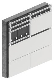
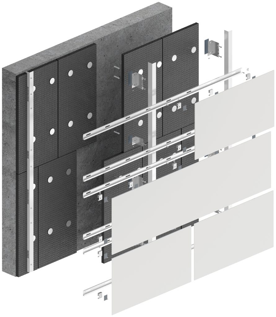
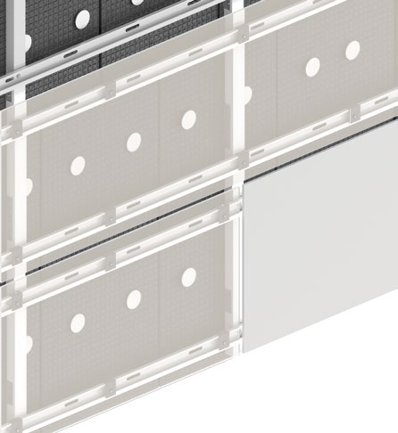
Manufacturer exploded DKT1 system showing panel, anchors, rails, profiles, insulation and wall

DKT1 system detail

The complete support path

Each layer connects the finished panel back to the wall.

25
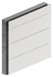
DKT1 horizontal rails and panel joint reference

DKT1 system detail

Rails set the panel joints

Rail spacing and hanger locations set the support points behind the panels.

26
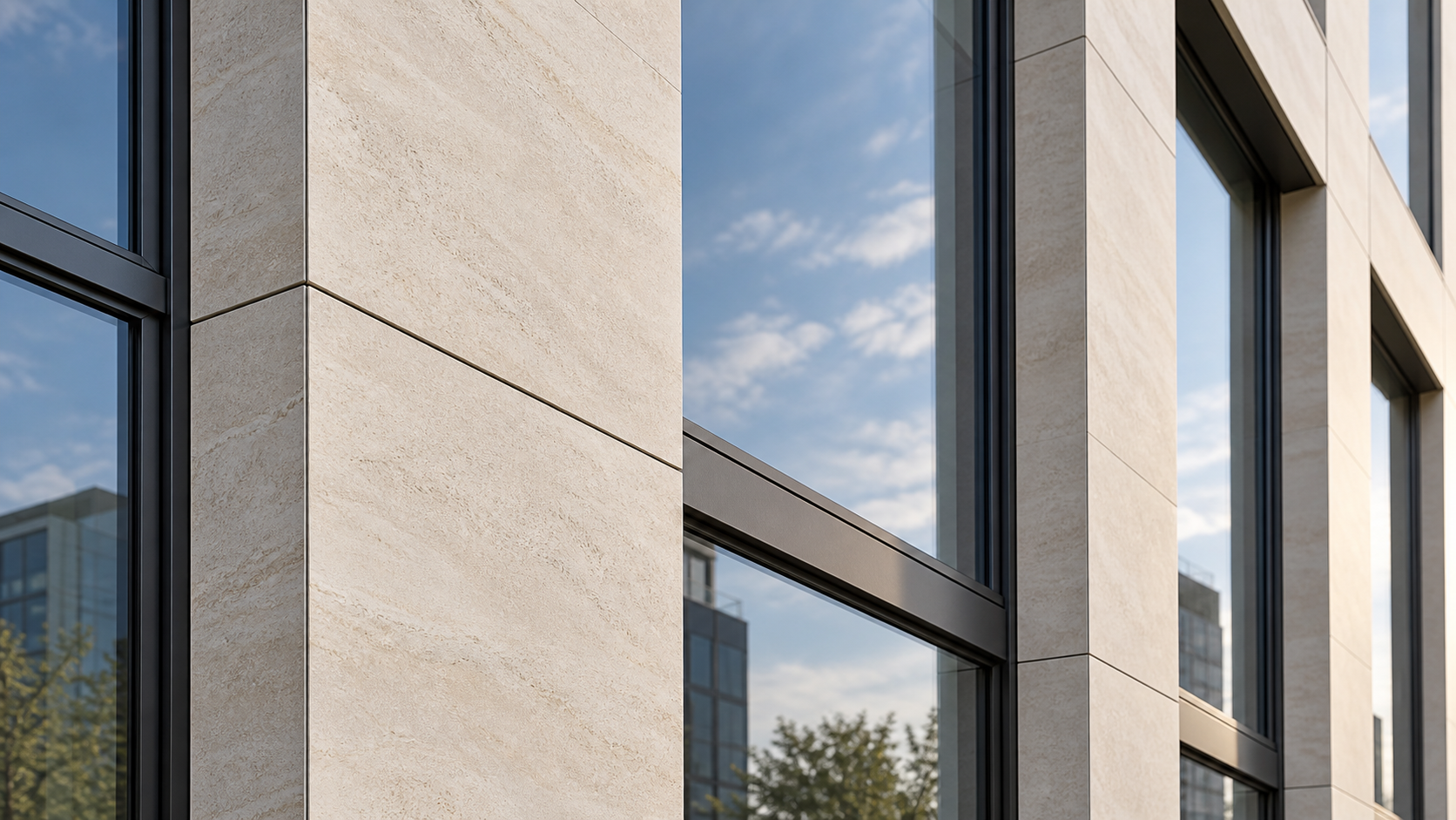
Illustrative close-up of finished limestone-tone panels and glazing

Panel selection

The proposed panel thickness

The current proposal uses thicker panels at ground level.

8 mm
Typical field
10 mm
At grade
  • Select anchors to suit the panel thickness.
  • Confirm embed depth and stamped calculations.
27

Dekton data

The panel material

Low water absorption and frost resistance support exterior use.

PropertyPublished value
8 mm panel weight4.10 lb/ft²
12 mm panel weight6.00-6.40 lb/ft²
Water absorption0.1%
Thermal movement5.1-6.5 × 10⁻⁶ /°C
8 mm flexural resistance50-55 N/mm²
12 mm flexural resistance48-54 N/mm² by family
28
1. Set wall brackets
2. Install insulation
3. Align vertical profiles
4. Set horizontal rails
5. Hang panels
5. Hang panels
6. Check the finished field

DKT1 assembly

Six steps to the finished wall

Each stage sets the line for the next.

29
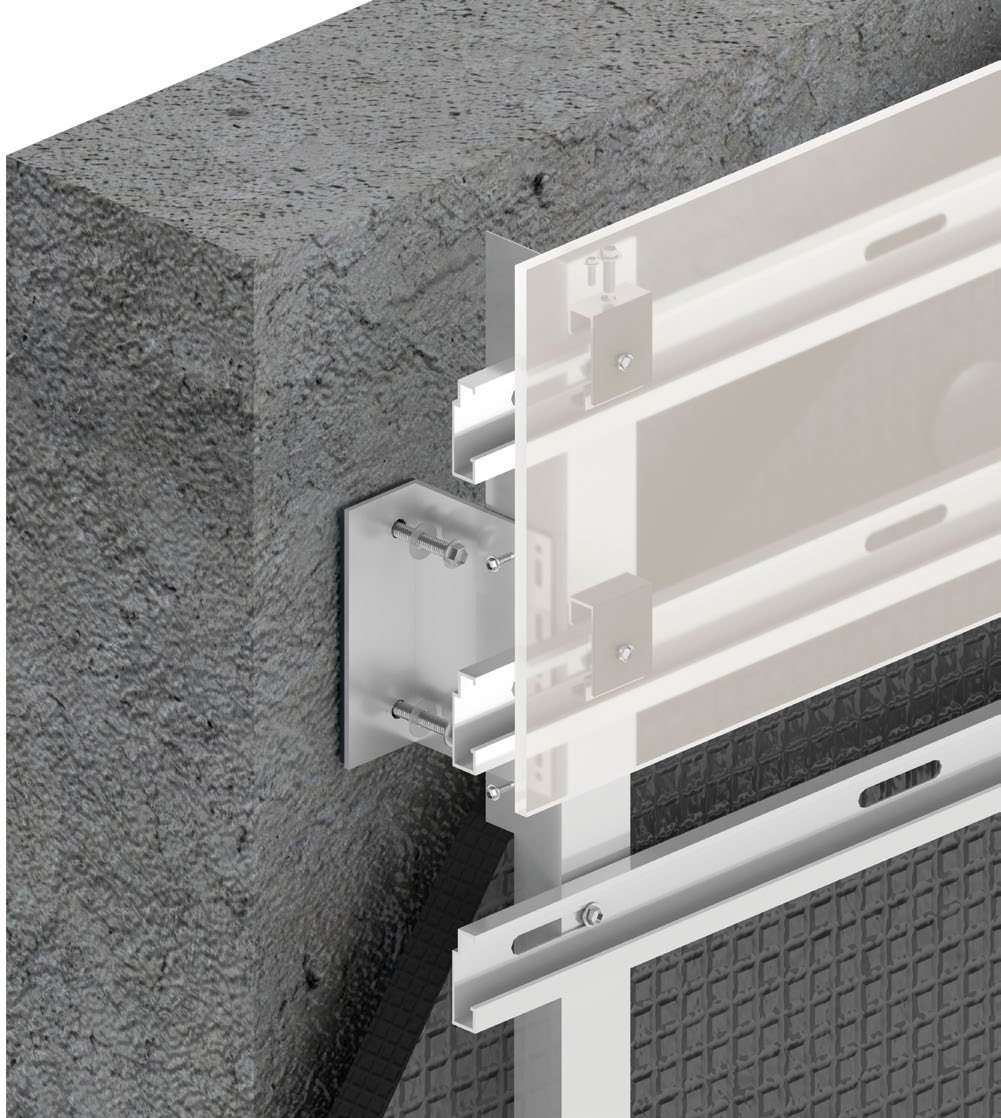
Manufacturer wall bracket, profile, insulation and carrier rail detail

DKT1 subframe

The wall bracket

The wall bracket anchors the frame behind the panels.

30

IGS schedule · Design

Design and approvals

Samples, design assist and tower submittals · September 2026 – January 2027

Design / approvals
Workstream
20262027
SepOctNovDecJan
  1. Sample submittals30 Sep – 21 Oct 2026
  2. Design assist30 Sep – 8 Dec 2026
  3. Embed drawings23 Oct – 19 Nov 2026
  4. Embed review + records9 Dec 2026 – 28 Jan 2027
  5. Curtainwall submissions15 Oct – 14 Dec 2026
  6. Tower approval + calcs15 Dec 2026 – 7 Jan 2027
31

IGS schedule · Main facade

Level-by-level installation

Level 1 through level bulkhead · 24 May – 27 August 2027

Installation
Workstream
2027
MayJunJulAug
  1. Level 124–31 May 2027
  2. Level 21–11 Jun 2027
  3. Level 314–28 Jun 2027
  4. Level 429 Jun – 12 Jul 2027
  5. Level 513–26 Jul 2027
  6. Level 627 Jul – 9 Aug 2027
  7. Level 710–18 Aug 2027
  8. Level bulkhead19–27 Aug 2027
32

Delivery schedule

Turkey to Nashville

U.S.-based IGS · Manufacturing in Turkey

DesignProcure / fabricateDeliveryInstall / handover
Workstream
202620272028
Sep–DecQ1Q2Q3Q4Q1
  1. Samples + design assistThrough 8 Dec 2026
  2. EmbedsHandover · 17 Mar 2027
  3. Curtainwall + DektonFinal package · 7 Feb 2028
  4. Storefront + podiumInstall through 20 Jan 2028
  5. Entrance doorsInstall through 17 Feb 2028
  6. Glass railingsInstall through 21 Mar 2028
33

IGS schedule · Delivery windows

Deliveries and handovers

Scheduled deliveries and the site work that follows.

PackageDelivery windowFirst site activity
Embeds8–10 Mar 2027Handover
11–17 Mar 2027
Curtainwall + Dekton6 Apr – 7 May 2027Level 1
24–31 May 2027
Entrance doors7–14 Oct 2027Door installation
21 Jan – 17 Feb 2028
Storefront + podium2–29 Nov 2027Layout
30 Nov – 2 Dec 2027
Glass railings15–22 Feb 2028Railing installation
23 Feb – 21 Mar 2028
34

IGS schedule · Remaining packages

Final site sequence

Storefront, zipper, bulkhead, doors and railings · November 2027 – March 2028

Installation
Workstream
20272028
NovDecJanFebMar
  1. Layout + waterproofing30 Nov – 16 Dec 2027
  2. Storefront + punch windows17 Dec 2027 – 20 Jan 2028
  3. Zipper / hoist run22–31 Dec 2027
  4. Bulkhead curtainwall + panels3 Jan – 7 Feb 2028
  5. Entrance doors21 Jan – 17 Feb 2028
  6. Glass railings23 Feb – 21 Mar 2028
35
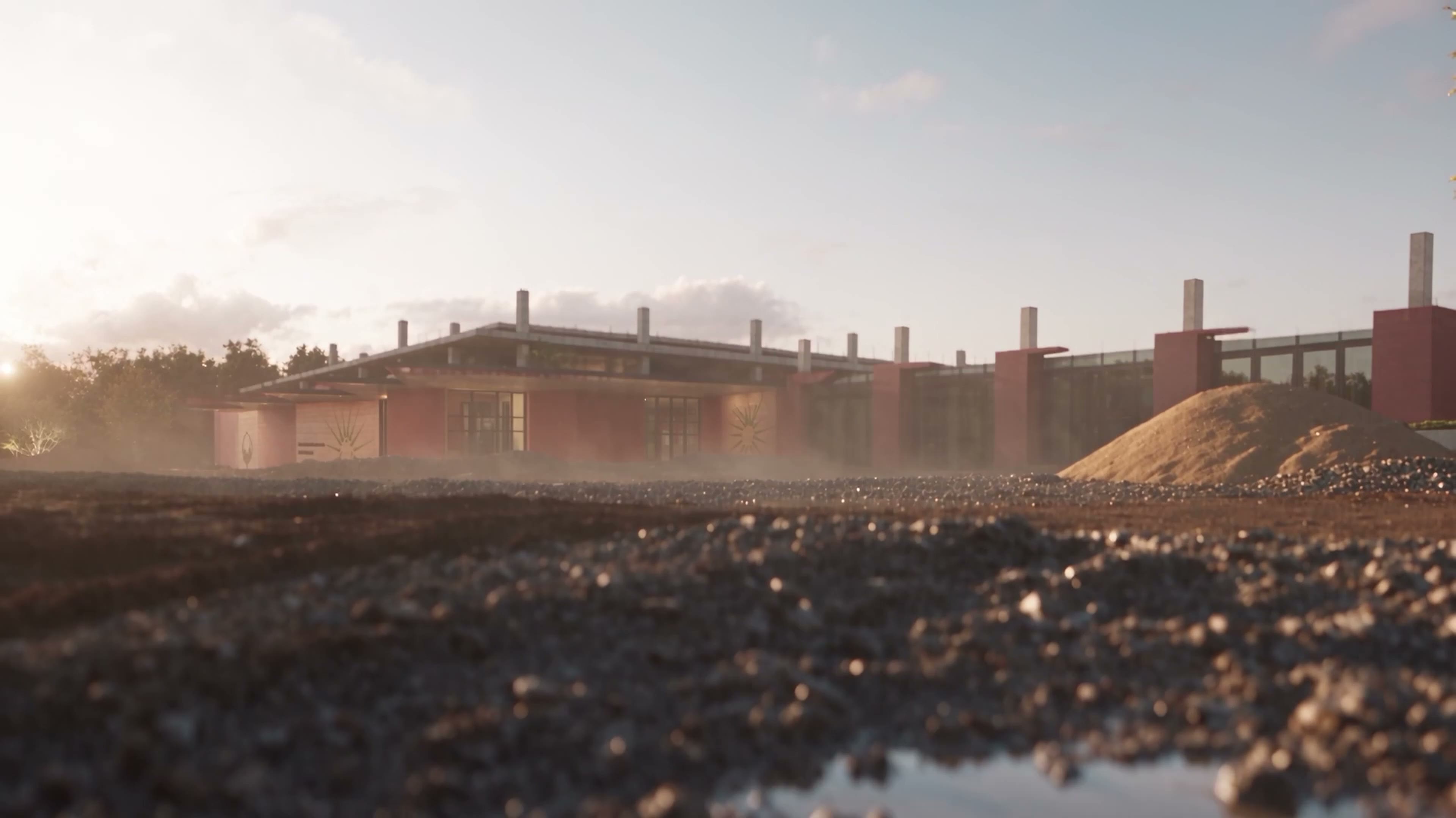
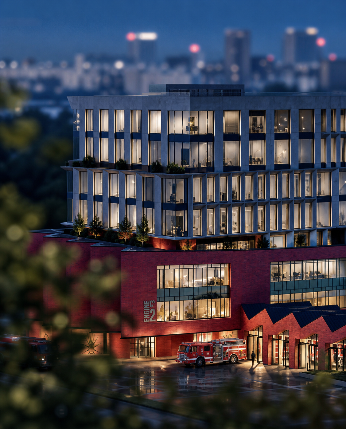
Metro Nashville Fire Department building visualization

1CG + Clark Construction

One facade.
One team.

1CG coordinates glass, panels and connections from shop drawings through closeout.

36

Metro Nashville Fire Department

A new homefor our heroes

Headquarters and Fire Station 2

Upper office volume and facade openings

The project

One connected facade

The fire station, headquarters and office building share one facade plan.
555'-4"
Roof elevation
13'-4"
Typical floor to floor
24'-8"
Typical tall unit
  • Tall windows serve the upper floors.
  • Terraces step back above the working base.
03
Typical tall glazing unit in the project model

Our scope

The facade scope

1CG coordinates the glass, panels and the places they meet.
42,752 SF
Facade glazing
2,900 SF
Doors and louvers at grade
940 SF
Terrace railings
  • All floors, including ground level: factory-built glass and panel units.
  • Entrances, base-bid storm-rated louvers, terrace rails and ACM coping.
  • Perimeter seals, flashings and connections.
  • Brick, signage and logo etching: excluded.
  • Bi-fold apparatus doors: separate alternate.
04
Facade installation shown in the standalone 1CG brand film

1CG + IGS

The people behind the work

One team connects design, manufacturing and installation.

Tony

Unitized-glazing experience in the US and overseas, including three supertall projects.

10.8M SF domestic8.8M SF internationalSelected experience: Freedom Tower, Shanghai Tower and projects in the UAE.

1CG

One point of contact for the facade, from drawings through closeout.

About 1.6M SF of glass experience with IGS

IGS

IGS is a U.S.-based company with manufacturing plants in Turkey, supporting glass, panels and factory-built units.

Production, packing and shipping coordination
—
West elevation
West elevation
East elevation
East elevation

Project drawings

West and east elevations

Opening sizes and panel joints follow the elevations.
05
Overall north elevation
IGS · C02 · Detail 1
Overall south elevation
IGS · C02 · Detail 3

IGS project elevations

North and south elevations

North and south elevations coordinate the window grid, stepped terraces and apparatus base.
06
Project glazing and window detail

Performance basis

Built for the required loads

The glass, frame and anchors must work together under the governing load.
Level D
Missile criterion
1-5/16 in.
Current impact IGU basis
ASCE 7-22
Chapter 32 tornado basis
  • Risk Category IV is the project basis.
  • Evaluate tornado and code wind loads. The larger case governs.
  • The structural glass interlayer carries the impact requirement.
07
Still from the supplied model installation video

Glass and framing

Built in the factory. Set on site.

Glass and panels arrive as coordinated, factory-built units on every floor, including the ground floor.

AAMA 2604
Powder-coat basis
20 years
Finish warranty basis
10 years
System and glass warranty basis
  • IGS is U.S.-based, with manufacturing plants in Turkey.
  • Set glass, gaskets and finishes before delivery.
  • Plan tolerances and connections together.
08

Assembly in motion

The system comes together

Glass, framing and panels align as one assembly.
Enlarged north/east elevation, Level 7 to roof
IGS · C03 · Detail 1
Enlarged east/north elevation, Level 7 to roof
IGS · C03 · Detail 3

IGS enlarged elevations

The upper-floor facade

Enlarged elevations show how the panel profiles frame the glazing from Level 7 to the roof.
  • Glazing and panel alignment
  • Level 7 through roof
  • Dimensioned bays and grid lines
10
Typical intermediate precast profile
IGS · SD101 · Detail 1

IGS profile detail

The panel profile at the window

The profile detail shows the glazing, insulated backpan and angled panel returns in one section.
  • Vision and spandrel glazing
  • Insulated backpan
  • Interior finishes by others
11
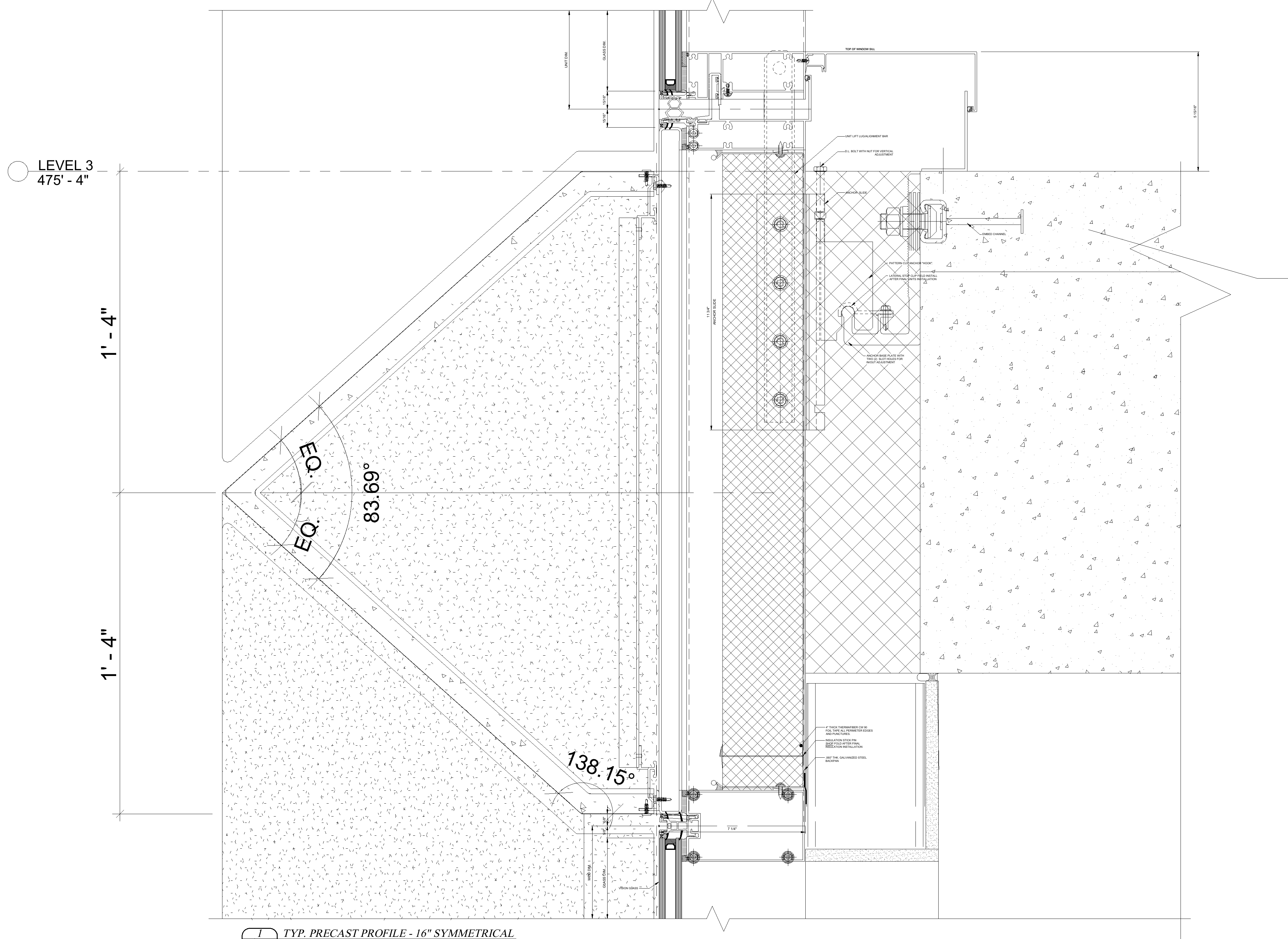
Typical precast profile, 16-inch symmetrical, at Level 3
IGS · SD104 · Detail 1

IGS profile detail

The Level 3 panel connection

The symmetrical profile meets the glazing and adjustable anchor assembly at Level 3.
  • 16-inch symmetrical profile
  • Embed channel and anchor slide
  • Vertical adjustment bolt
12
Project model of apparatus-bay and grade-level openings

Doors and louvers

Openings at ground level

Doors, louvers and storefront must work with the building’s access and security systems.

2,000 SF
Bi-fold door alternate
900 SF
Storm-rated louvers
  • Coordinate locks, wiring paths and access control.
  • Confirm automatic operators where required.
  • Bi-fold apparatus door pricing is a separate alternate.
  • Storm-rated louvers are included in the base bid.
13
Supplied vision-glass detail

Vision glazing

The glass makeup

Deep Silver glass sets the look. A structural interlayer supports the impact requirement.
  • Outer lite: 8 mm Ecosol T 35 Deep Silver.
  • Space: 12 mm, filled with 90% argon.
  • Inner laminated lite: 6 mm ultra-clear glass with a .090 SGP interlayer.
  • Confirm vision, spandrel and impact build-ups, plus thermal values, before release.
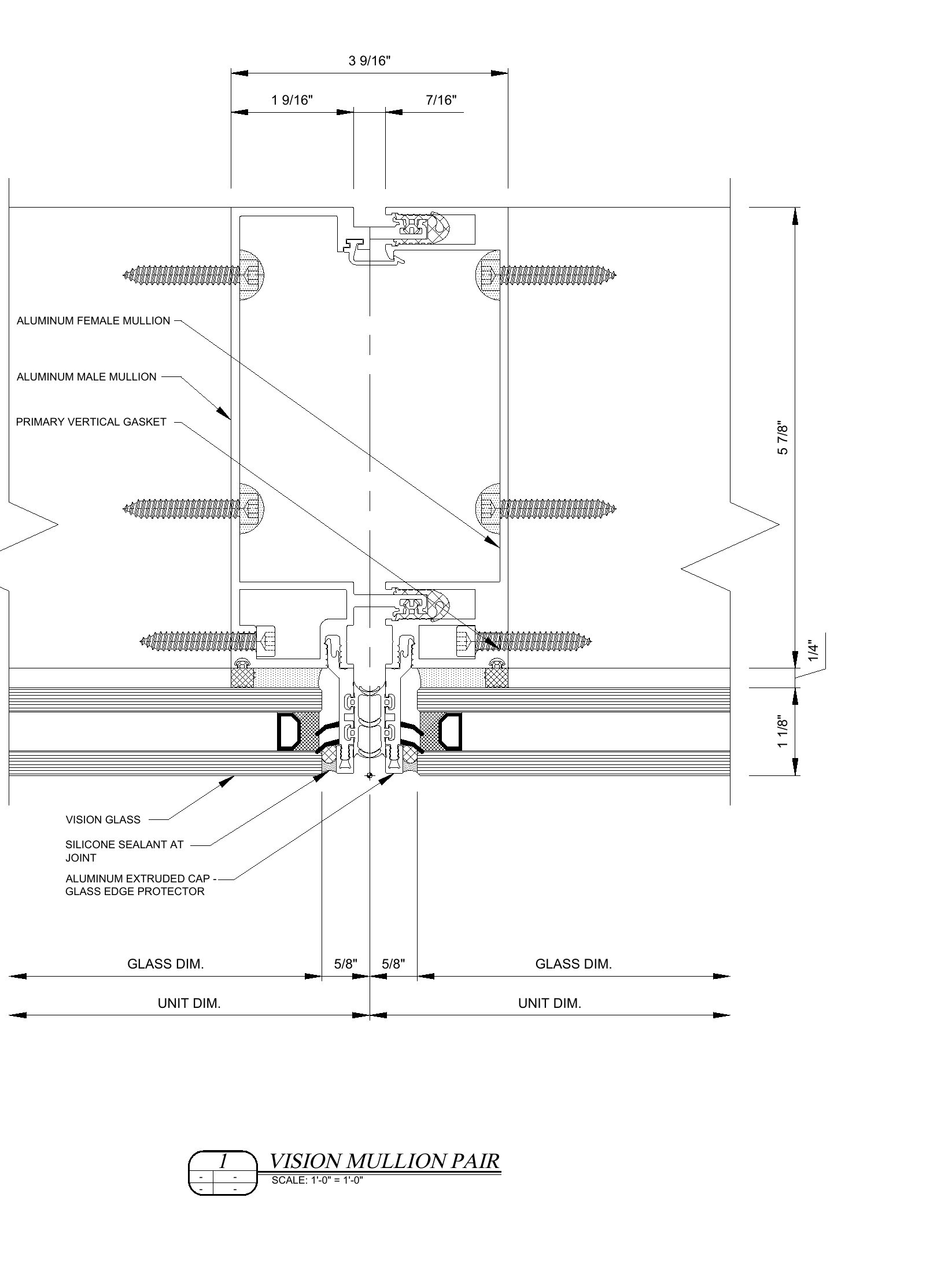
14
Vision mullion pair with gasket, sealant and glass-edge protector
IGS · SD100 · Detail 1

Framing detail

The vision-glass joint

Male and female aluminum mullions join adjacent vision-glass units around a primary vertical gasket.
  • Paired aluminum mullions
  • Primary vertical gasket
  • Sealant and glass-edge cap
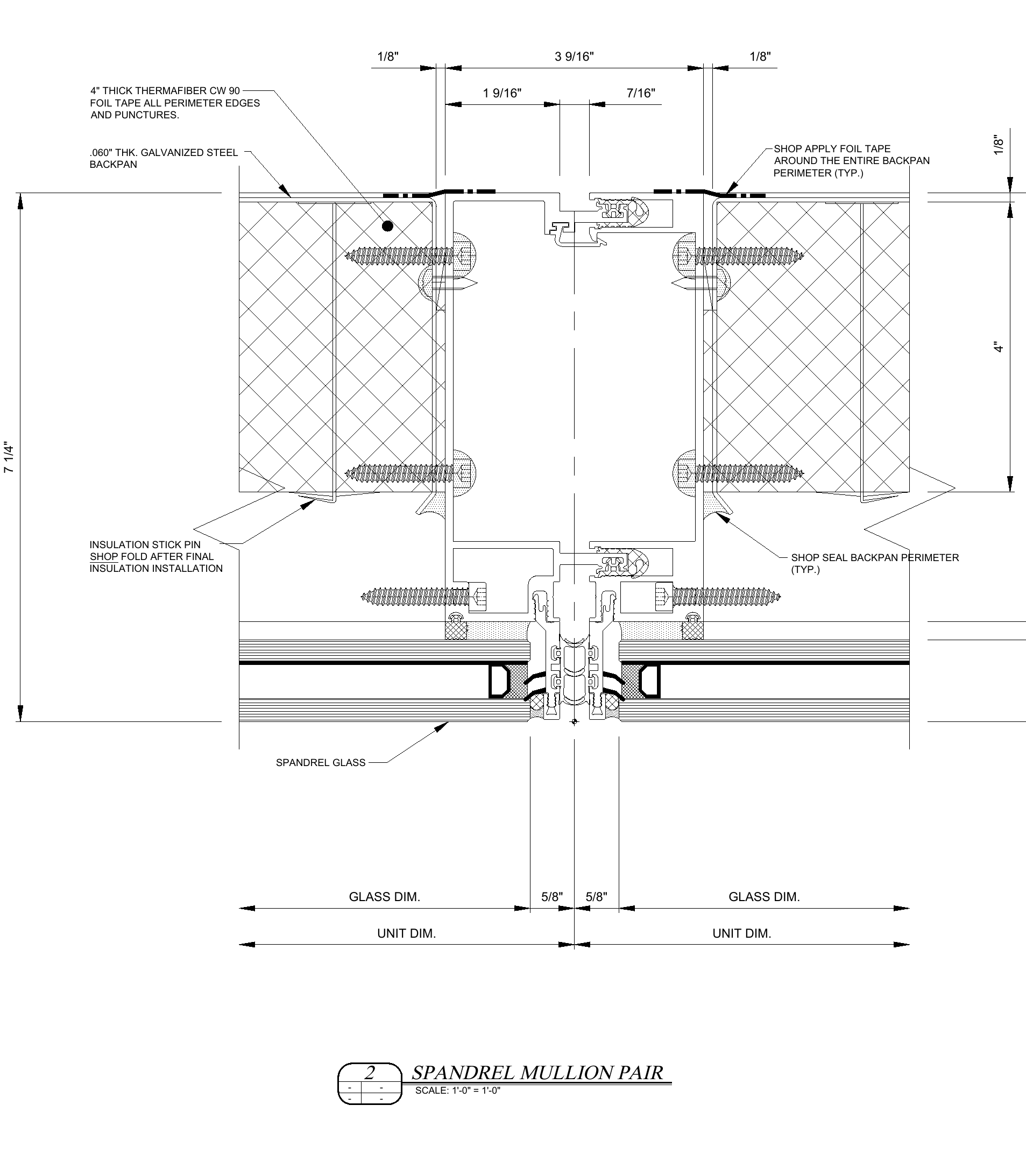
15
Spandrel mullion pair with insulated galvanized steel backpan
IGS · SD100 · Detail 2

Framing detail

The spandrel joint

The spandrel joint combines the paired frame with an insulated, shop-sealed steel backpan.
  • 4-inch Thermafiber CW90
  • .060-inch galvanized backpan
  • Shop-sealed and foil-taped edges
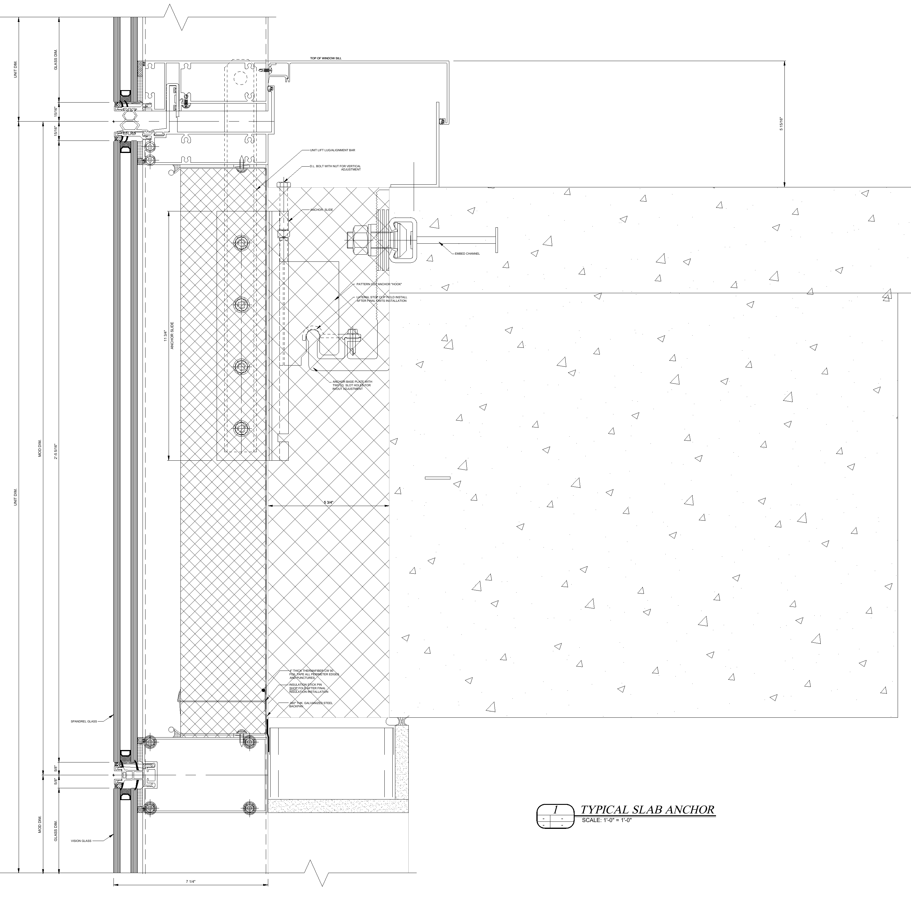
16
Typical slab anchor with embed channel, adjustment bolt and lateral stop clip
IGS · SD102 · Detail 1

Framing detail

The slab connection

The embed channel and anchor assembly connect the unit to the slab with vertical and in/out adjustment.
  • Slotted anchor base plate
  • Vertical adjustment bolt
  • Field-installed lateral stop clip
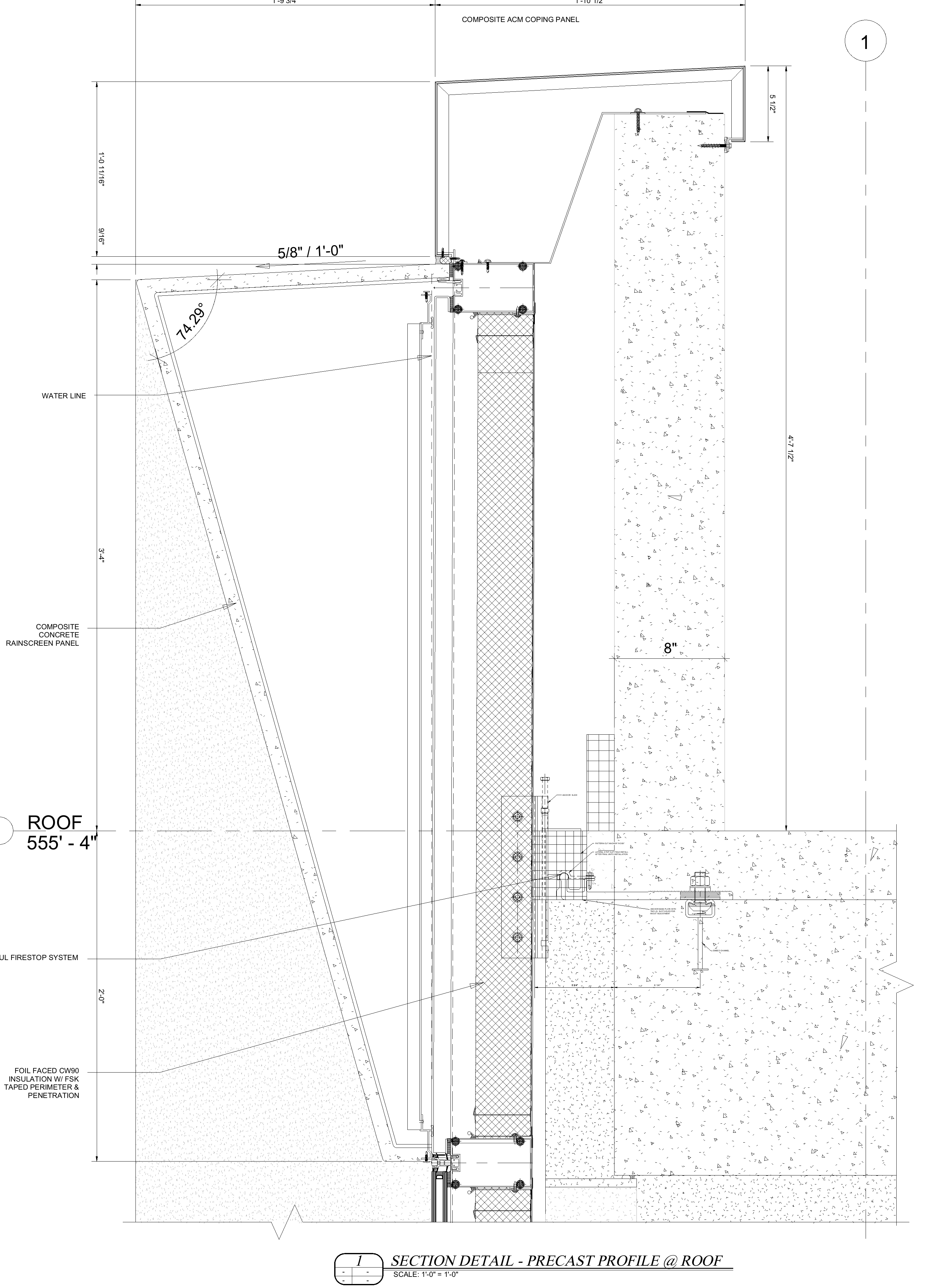
17
Roof profile section, rotated upright
IGS · SD103 · Detail 1

Framing detail

The roof connection

The roof section brings together the coping, water line, insulated enclosure and slab anchor.
  • Coping and water line
  • Foil-faced CW90 insulation
  • Firestop interface at the slab
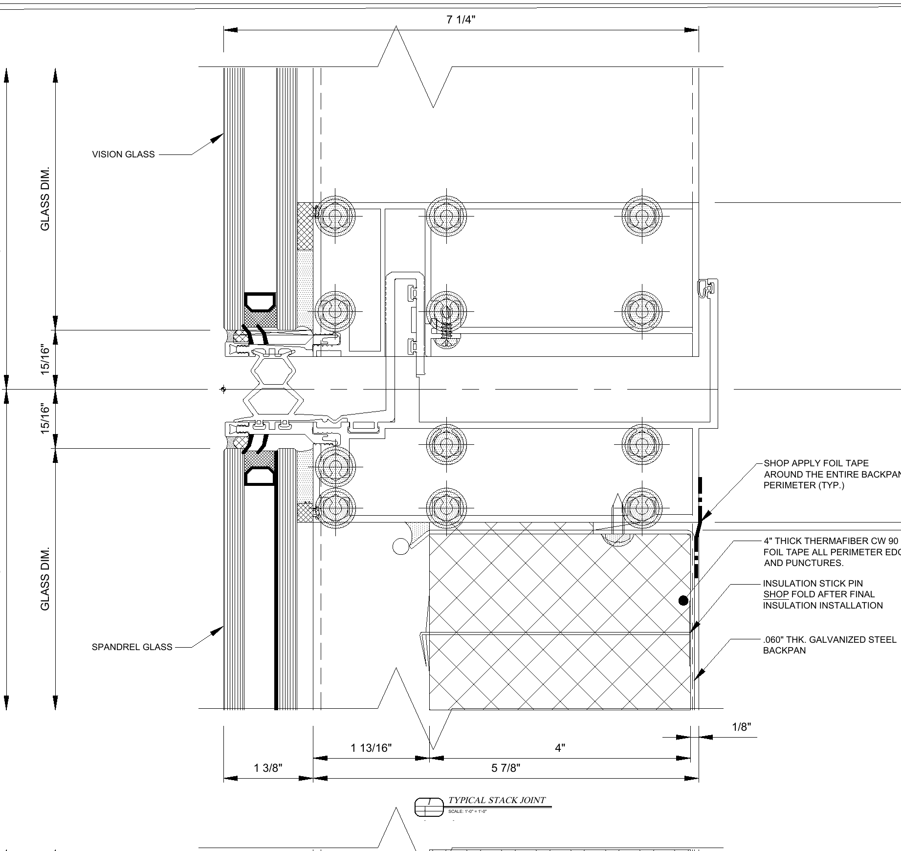
18
Typical stack joint between vision and spandrel units
IGS · SD106 · Detail 1

Framing detail

The joint between units

The horizontal stack joint connects the vision unit above to the insulated spandrel zone below.
  • Interlocking frame profiles
  • Vision-to-spandrel transition
  • Shop-taped backpan perimeter
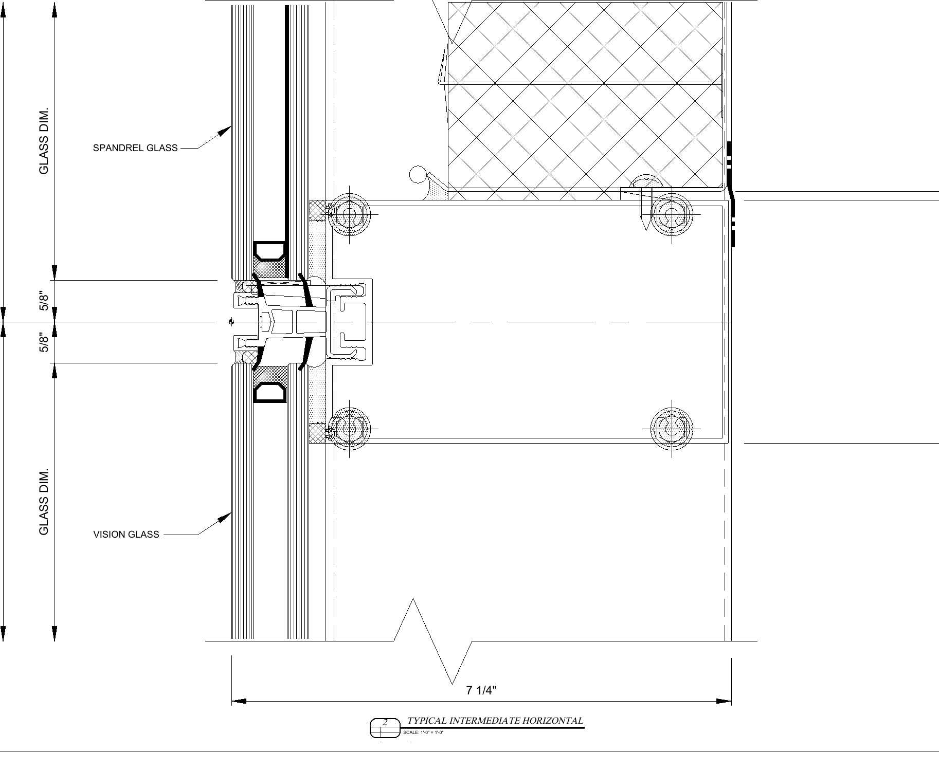
19
Spandrel-to-vision intermediate horizontal
IGS · SD106 · Detail 2
Vision-to-vision intermediate horizontal
IGS · SD106 · Detail 3

Framing details

The intermediate joints

The two horizontal details show the frame connections at spandrel-to-vision and vision-to-vision transitions.
  • Spandrel-to-vision joint
  • Vision-to-vision joint
  • 7¼-inch frame depth shown
20
Illustrative terrace glass guardrail and tube handrail

Terrace railings

A clear terrace edge

Glass and tube rails follow the stepped terraces.
940 SF
Glass and tube railings
  • Coordinate anchors, guard heights and slab edges.
  • Keep the waterproofing continuous at each fixing.
21
Panel and glazing interface at the facade corner

Perimeter details

A continuous water line

Seals and flashings must connect across every change in material.

  • Carry coping across the parapets.
  • Detail flashings at heads, curbs and louvers.
  • Connect concrete, masonry, metal, roofing and waterproofing.
  • Maintain two complete perimeter sealant lines.
22
Architectural reference for integrated panel and glass geometry

Material alignment

Glass and panels in one grid

Deep Silver glass, light panels, coated aluminum and the red soffit form one facade.
  • Align panel joints with the window grid.
  • Resolve returns, corners, coping and base connections before release.
23
Manufacturer view of the panel back and concealed fixings

DKT1 panel system

How the panels are held

Concealed anchors connect panels to hangers and rails. Wall brackets carry the frame.
  • Undercut anchors sit behind the panel face.
  • Upper anchors carry panel weight.
  • The remaining anchors resist wind loads.
  • Engineer the panel, anchors, rails and wall as one load path.
24
Manufacturer exploded DKT1 system showing panel, anchors, rails, profiles, insulation and wall

DKT1 system detail

The complete support path

Each layer connects the finished panel back to the wall.
25
DKT1 horizontal rails and panel joint reference

DKT1 system detail

Rails set the panel joints

Rail spacing and hanger locations set the support points behind the panels.
26
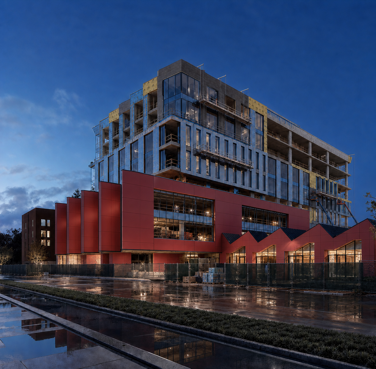
Illustrative close-up of finished limestone-tone panels and glazing

Panel selection

The proposed panel thickness

The current proposal uses thicker panels at ground level.

8 mm
Typical field
10 mm
At grade
  • Select anchors to suit the panel thickness.
  • Confirm embed depth and stamped calculations.
27

Dekton data

The panel material

Low water absorption and frost resistance support exterior use.

PropertyPublished value
8 mm panel weight4.10 lb/ft²
12 mm panel weight6.00-6.40 lb/ft²
Water absorption0.1%
Thermal movement5.1-6.5 × 10⁻⁶ /°C
8 mm flexural resistance50-55 N/mm²
12 mm flexural resistance48-54 N/mm² by family
28
1. Set wall brackets
2. Install insulation
3. Align vertical profiles
4. Set horizontal rails
5. Hang panels
5. Hang panels
6. Check the finished field

DKT1 assembly

Six steps to the finished wall

Each stage sets the line for the next.
29
Manufacturer wall bracket, profile, insulation and carrier rail detail

DKT1 subframe

The wall bracket

The wall bracket anchors the frame behind the panels.

30

IGS schedule · Design

Design and approvals

Samples, design assist and tower submittals · September 2026 – January 2027

Design / approvals
Workstream
20262027
SepOctNovDecJan
  1. Sample submittals30 Sep – 21 Oct 2026
  2. Design assist30 Sep – 8 Dec 2026
  3. Embed drawings23 Oct – 19 Nov 2026
  4. Embed review + records9 Dec 2026 – 28 Jan 2027
  5. Curtainwall submissions15 Oct – 14 Dec 2026
  6. Tower approval + calcs15 Dec 2026 – 7 Jan 2027
31

IGS schedule · Main facade

Level-by-level installation

Level 1 through level bulkhead · 24 May – 27 August 2027

Installation
Workstream
2027
MayJunJulAug
  1. Level 124–31 May 2027
  2. Level 21–11 Jun 2027
  3. Level 314–28 Jun 2027
  4. Level 429 Jun – 12 Jul 2027
  5. Level 513–26 Jul 2027
  6. Level 627 Jul – 9 Aug 2027
  7. Level 710–18 Aug 2027
  8. Level bulkhead19–27 Aug 2027
32

Delivery schedule

Turkey to Nashville

U.S.-based IGS · Manufacturing in Turkey

DesignProcure / fabricateDeliveryInstall / handover
Workstream
202620272028
Sep–DecQ1Q2Q3Q4Q1
  1. Samples + design assistThrough 8 Dec 2026
  2. EmbedsHandover · 17 Mar 2027
  3. Curtainwall + DektonFinal package · 7 Feb 2028
  4. Storefront + podiumInstall through 20 Jan 2028
  5. Entrance doorsInstall through 17 Feb 2028
  6. Glass railingsInstall through 21 Mar 2028
33

IGS schedule · Delivery windows

Deliveries and handovers

Scheduled deliveries and the site work that follows.

PackageDelivery windowFirst site activity
Embeds8–10 Mar 2027Handover
11–17 Mar 2027
Curtainwall + Dekton6 Apr – 7 May 2027Level 1
24–31 May 2027
Entrance doors7–14 Oct 2027Door installation
21 Jan – 17 Feb 2028
Storefront + podium2–29 Nov 2027Layout
30 Nov – 2 Dec 2027
Glass railings15–22 Feb 2028Railing installation
23 Feb – 21 Mar 2028
34

IGS schedule · Remaining packages

Final site sequence

Storefront, zipper, bulkhead, doors and railings · November 2027 – March 2028
Installation
Workstream
20272028
NovDecJanFebMar
  1. Layout + waterproofing30 Nov – 16 Dec 2027
  2. Storefront + punch windows17 Dec 2027 – 20 Jan 2028
  3. Zipper / hoist run22–31 Dec 2027
  4. Bulkhead curtainwall + panels3 Jan – 7 Feb 2028
  5. Entrance doors21 Jan – 17 Feb 2028
  6. Glass railings23 Feb – 21 Mar 2028
35
Metro Nashville Fire Department building visualization

1CG + Clark Construction

One facade.
One team.

1CG coordinates glass, panels and connections from shop drawings through closeout.

36
01 / 36
Projects